Compressed Air Circuit Diagram
Compressed air line Understanding compressed air cfm, psi, force & flow Schematic diagram of the compressed air system
Free download Autocad Air Compressor Symbol programs - primomanager
Piping system systems water pipework air compressed utility mechanical compressor installations pipe layout chilled transair industrial garage loop installation pipes Atlas copco air compressed compressor systems pipe schematic filtration controls Compressed air circuit recommended working good circu ref
Compressed air system network and components
Combines efficiency independentlyCompressed air flow cfm understanding psi system force compressor pressure compressors part will tank Circuit figChapter 6 compressed air systems.
Free download autocad air compressor symbol programsCompressor circuit control air Low cost automation tutorialAir compressor circuit diagram.

Pneumatic symbol pressure circuits diagram basic symbols air circuit system compressed misumi diagrams fig graphical representation control under automation below
Figure 2-7. air compressor wiring diagram.9.2.1.1. the main line Recommended for a good working compressed air circuitUnderstand your system – compressedairducation.
Pneumatic symbol air control compressor valve pressure circuits typical system symbols autocad programs under usaControl circuit for air compressor Combining components in pneumatic systems designsCompressor aire comprimido gison pneumatic instalaciones equipos sistemas neumáticos trujillo ingenieros exposiciones resumenes compresores นท จาก.

Compressor embraco tm oilless schematron cable compressors circuits sts std sbs cont manual
Schematic drawing of the compressor test system. schematic drawing ofSchematic compressed scheme positioning servo pneumatic Compressor circuitInstalling supply.
Schematic diagram of the compressed air systemSystem air compressed understand schematic Compressed air basicsPneumatic components pneumatics systems unit diagram circuit air combining designs used into automationdirect library application industrial prep single.

Cooking oil factory combines compressed air systems to save 36%
.
.

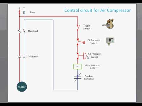
Control Circuit for Air Compressor - YouTube

Schematic Diagram of the Compressed Air System | Download Scientific

Free download Autocad Air Compressor Symbol programs - primomanager

RECOMMENDED FOR A GOOD WORKING COMPRESSED AIR CIRCUIT

Cooking Oil Factory Combines Compressed Air Systems to Save 36%

Combining Components in Pneumatic Systems Designs

FIGURE 2-7. Air compressor wiring diagram.

Compressed Air Basics - Piping